CHAPTER
XI
FRANK HORNBY AS AN EDUCATOR.
After Frank Hornby had made an international success of his Meccano business he became interested in working out a system of mechanical demonstration for schools and colleges. A great demand had come for Meccano sets, for use in class rooms, to show or demonstrate just what a "Diagonal Tie" is, or a "Braced Tower," or a "Trestle," or a "Universal Crosshead," or a "Block and Tackle," and all the other mechanical principles which the student must learn before he can succeed. So Frank Hornby prepared a book entitled "The Hornby System of Mechanical Demonstration." The following pages are a reprint and explanation from that book.
It is printed
here for the boy who wants to work hard with his Meccano and really learn
the principles of mechanics. It will be especially valuable to the boy
who wants to be an engineer, architect, manufacturer or high-salaried
mechanic. The advantage of Meccano in teaching the principles of mechanics
is that a model can be built, studied and demonstrated, and then taken
apart and the parts used to construct other models; also the boys who
go to scientific schools, learn the principles of mechanics and of mechanical
science by making their own models and in that way having a lot of fun
and learning useful things at the same time. This is just exactly what
any boy can do at home with Meccano. He can have no end of fun playing
with Meccano and at the same time find out about the different ways that
construction work, bridge building, machine operation and electrical work
are carried on by the big, real engineers.
First, he can make a Simple Roof Truss, like this one, and learn one of
the first principles that an engineer is taught. This is the increased
strength that is secured by using a girder bent at right angles, as shown
by numbers 1, 2, 3 and 4 in the picture. This girder has much more strength
than the single strip because no matter which way the strain comes there
is always an edge the opposite way which stands the strain without bending.
The greater strength secured in this way is the reason you see these right-angle
girders used in building large bridges, buildings, tanks and other steel
constructional work.

This same principle is still further followed out in the Built-up Girder. This picture shows a simple type of built-up girder such as is used frequently in bridge construction.

The diagonal,
or slanting part of this Built-up Girder and the top, horizontal part
are constructed of right-angle strips, while the vertical supports and
the lower horizontal part are constructed of flat strips. The upper boom
of a girder like this is always in compression, meaning that there is
always a strain on it, and therefore needs to be strong and rigid. The
lower boom (2a) is in tension; meaning that it merely holds the other
part in position; and therefore needs to be only a flat strip. This Built-up
Girder is also used in bridge building-you can see enormous big ones just
like it in almost any bridge.
Isn't it perfectly wonderful when you think of the enormous big suspension bridges that span our great rivers; when you think of the great engineers who plan and construct these bridges; and then when you think that you can build just exactly the way these great engineers do? But big and small structural work is not the only thing Meccano teaches boys. In fact, the boy who has a Meccano outfit today can reproduce in miniature practically any mechanical, electrical or structural machine or structure he has ever seen or that he can imagine. In the mechanical or machinery line particularly, any boy can find a vast treasure of things to make. You have surely been in a great machine shop where belts, and pulleys, and shafts were whirling around overhead. A picture of such a shop is shown in this book.
In these machine shops, where machines that can be driven forward and be reversed are used, open and crossed belt drives are used to run them. This picture shows how open and crossed belt drives work. The crank shaft, which is the shaft' with the handle (5), runs through the holes in the long strips, and the pulley wheels on this shaft are securely fastened to the shaft. The second shaft (7) is also run through the holes in the strip, but the pulleys on this shaft are loose, so that they will turn and the shaft will not. The nearest belt-and for belts, rubber bands are used-is an open drive, while the one further away is a crossed belt drive.
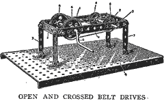
By turning the crank, the wheels on that shaft turn both in the same direction, but the pulleys on the other shaft turn in opposite directions. With the open drive, both the driving and the driven pulleys turn in the same direction; but with the crossed belt drive, the driving pulley turns the opposite direction. So you see how in machine shops where belt driven machines are used, when the engineer wants a machine to run in the same direction that the driving shaft runs, he puts on an open drive, but when he wants the machine to run in the opposite direction, he puts on a cross belt drive. If you have ever seen one of the old ferry boats that run back and forth across the rivers with its old style side paddle wheels and the big walking beam moving up and down, up and down, way up on the top of the boat, you must have often wondered how the engine that turns that big paddle wheel works.
Of course you know it is a steam engine. But do you know how a steam engine works ? Let me tell you how it works, and show you how you can build an engine like this with Meccano. The power as it comes directly from the engine produces only one kind of motion; a to-and-fro, back-and-forth or in-and-out motion. The steam is injected into the cylinder and when it rushes in, it forces the piston out. Each time the piston moves in and out of the cylinder, the steam is likewise rushing in and out, and so forcing the piston to do the same. Of course, the action of the piston is so rapid that you can hardly see it move in and out, but that is the way the steam engine is able to go so fast; that is why the locomotives of to-day are able to pull the big, long express trains across the country and travel 60 and 70 miles an hour. But the paddle wheels on the steam- boat do not move in and out, they move round in a circle, or as the engineers call it, they have a rotary motion.
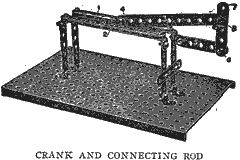
Now, to change the to-and-fro motion of the steam engine into a rotary motion of the paddle wheels, a crank and connecting rod is used. This picture shows the action of a crank and connecting rod of an engine. The guide strips (1 and 2) are the cylinder and the connecting rod is 3. An angle bracket is bolted to the end of the connecting rod at 4, and slides in and out between the guide strips. This angle bracket represents the piston.
This gives a to-and-fro motion to the angle bracket between the strips. The crank is 7. The connecting rod and crank are bolted together at 8 loosely so that when the piston is moved to-and-fro between the guide strips, the connecting rod will move in the same direction and the crank will take a rotary motion and move around in a circle, turning around on the bolt at No. 6. This simple model made of Meccano strips, shows the motion of the piston in the cylinder, and shows how the to-and-fro motion of the piston is changed by means of the connecting rod and crank into a rotary motion such as turns the paddle wheels of the ferryboats. Now look at this picture of a model walking beam engine, and you will see how the to-and-fro motion of the steam engine is changed, and transmitted to the paddle wheel of the boat. The flat strip moves up and down in the small grooved eye pieces (4). This strip is in turn fastened to the horizontal strip (7).
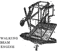
This horizontal strip is like the big walking beam that you see moving up and down way up on top of the boat. At the other end of the walking beam is another strip (9) which is attached to the wheel (10). This wheel is fastened to the shaft that runs across the frame and on the other end is the paddle wheel (12) that churns up the water and makes the boat go. This is the early form of the steam engine; one of the first types known as the single action engine. Still another interesting part of an engine is the Centrifugal Governor, which regulates the speed of the engine.
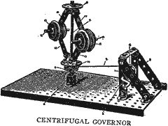
The various wheels and strips in the picture are attached to a vertical
or upright shaft. A pulley wheel is attached to the bottom of the shaft.
The top wheel is securely bolted to the shaft while the lower wheel is
left loose. When the crank is turned, the belt will turn the entire shaft.
As the crank is turned faster and faster, the wheel will rise up on the
shaft, spreading the weights further apart, and putting more strain on
the engine, thus requiring greater power to turn it around.
In a regular engine, when the lower wheel has worked up the shaft a certain distance, it automatically operates a lever which shuts off the steam from the engine and so controls the speed without the engineer having to watch it. Isn't that a wonderful thing ? After the steam engine in the factory, or in the steamboat, or in the locomotive, or anywhere else that a steam engine may be used has produced its power and its power has been transferred from a to-and-fro motion into a rotary motion, it is then often necessary to control the power so that it can be used in several different ways. For instance, the power produced by a big engine might be entirely too strong or too fast, or too slow, for some of the little machines that are run by steam power. Then the engineer must transform his power, must reduce it or must increase it-in other words, he must control his power so that it can be used in any way that he wants to use it.
He does this with gear wheels, as well as with belts. This picture shows the usual type of gear train used in engineering where it is necessary to reduce the velocity, or speed, of the power. The shaft (5) furnishes the power. That is, the power direct from the engine turns this shaft. But that shaft turns too fast. So the engineer uses a set of gear wheels to slow down the speed.
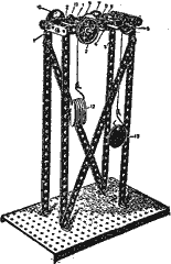
The fast moving shaft turns all the gear wheels that you see in this picture, until when the power reaches the shaft at the other end (2), it has been slowed down very considerably, and it is for use to run a machine that goes slower. But this method of reducing speed is expensive because it requires so many gear wheels and of course, the more gear wheels there are, the more attention they must have, the more likely they are to get out of order, the more trouble they might cause. So to overcome the inconvenience of the Gear Train, the Worm and Worm Wheel method is used instead in many places. In this case, the shaft (2) is the one which brings the power from the engine. When this shaft turns around at a high speed the toothed wheel (4) moves around very slowly. In fact, the shaft must turn around fifty times before the wheel will turn around once. This is because the worm drive (3a) is what is known as a single thread worm.
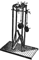
There are fifty teeth in the large wheel (4) and as the worm wheel engages only one of these teeth at a time, this worm wheel must turn around completely once before it engages a new tooth in the large wheel. Such an arrangement does the same work and fulfills the same principles as the complicated Gear Train, and it is a great advantage in engineering. It is often used to reduce the high speed at which an electric motor runs so that the power can be used for operating machines which must run slower
These are
but a few of the wonderful things about engineering that any boy can learn
with Meccano, and now, when you see what a very useful invention Meccano
is, do you wonder that Frank Hornby has reason to feel proud of his invention
and to feel, in the great praise which comes to him, well repaid for all
the time, thought and effort which inventing this wonderful toy involved?
Meccano-cal engineering is such fine fun for boys, because the boys can
build so many different things and because they build just like the big
engineers do. Meccano is the original and only constructional toy that
builds models that are true to mechanical and engineering principles.
Meccano isn't just a toy, it is a real education in mechanics and engineering.